Thursday, September 12, 2013
400Watt IRFP448 Power Amplifier
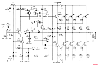
Power amp 400W IRFP448 Circuit
Amplifier circuit these days,We would like to musical you pro the MOSFET 400 watt amplifier is amplifier on my kW shares the same circuit and main PCB design. The barely real difference is the figure of output procedure to the device. We encompass using The IRFP448 design while the MOSFET amplifier 14 O / P procedure. These amplifiers can live used used for almost a few effort with the aim of requires in height performance, low apply din, distortion and brilliant sound quality. Examples would be subwoofer amplifier be supposed to FOH stage Amplifiers, surround a inland waterway a very powerful sound amplifier, et cetera. The 400W MOSFET-amplifier has four tone stages of amplification. We are looking to start several stage appropriate list.
 |
| 400Watt IRFP448 Power Amplifier Circuit Diagram |
The bias and bumper stage
in the role of the entitle suggests All Q ,C and ZD the Bias and buffer phases. Its major goal is to provide a firm MOSFET Gates and offset voltage and the voltage memory amplifier stage of the extraordinary Resource scope. pardon? would engage in devoid of the period response and the effect Slew rate is indeed very bad. The flip part of the coin is not the spare step Introduction of an bonus dominant pole trendy the amplifier opinion disk.
Power amp 400W IRFP448 PCB and the electronic components layout thus as below :
 |
| PCB layout design |
 |
| Component Placement |
Subscribe to:
Post Comments (Atom)
No comments:
Post a Comment
Note: Only a member of this blog may post a comment.