Saturday, November 9, 2013
Stereo to surround sound systems
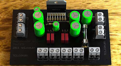
Circuit quad amplifier or stereo to surround sound systems using the ic tda7375 to power of 7 watts per channel amplifier version quad or dual 15-watt version (stereo). reaching up to 35 watts in mono version.

The TDA7375 is an integrated circuit quad amplifier class AB audio amplifier capable of working in double bridge or quad amplifiers simple integrated circuit protection system for short, requires minimal external components, available in packages multiwatt 15H (TDA7375H) and multiwatt 15V (TDA7375V). While the first design was for automotive applications, you can use it in a variety of low power applications. This integrated circuit is in an ideal situation where one wishes a reasonable power and a relatively low supply voltage for its operation. This circuit drawn below uses the basic configuration of amplifier quad configuration but using a bridge (Bridge), can be about 4 times the maximum power. In this configuration quad amplifier can be used as an amplifier end of surround sound systems when seven watts per channel has a good power using a minimum of components.

Operation of the circuit of the audio amplifier with tda7375
The capacitor C8 decouples the internal voltage divider. Capacitors C5 and C6 are the filter to the power supply. The capacitors 2200?F / 16V are output capacitors. Vs is the power supply can be a car battery or a source of 14 volts.
As suggested pleo friend Ronaldo, now this circuit is dynamic, with at least three variations of assembly, and Quad mount, bridge or stereo system 2.1 Stereo + Subwoofer bridge. Suffice it to set a jumper on the card and switch between P (bridge) and N (normal).
An ideal application is in conjunction of 2.1 systems subwoofer filter posted by Buddy A. Junior, which is used as channel 1 and 2 channel stereo and 2 and 3 in bridge mode to Subwwofer. In bridge mode the output capacitors should be omitted.
Anyway you will find the best application for the circuit
Circuit diagram of amplifier with tda7375 – now dynamic
It can be 12V/30VA with a transformer, a bridge rectifier and an electrolytic capacitor or 4700?F (highest). The maximum current consumption with loads of 4ohms is 2.1 A. You can use loads of 2 ohms, but remember also to increase the size of the heatsink, because the integrated circuit package multiwatt will heat a little more. The fuse circuit to be 2A to loads 4 ohms. The maximum voltage is to tda 18 volts, then the working voltage of the electrolytic capacitors is 35 volts. Recommend a source of 15 volts / 2 amps.
Suggested printed circuit board side of the copper
When assembling the circuit remember that this quad amplifier channels features two four inverted, then you should connect the speakers with the polarity reversed on these outputs, the polarity of electrolytic capacitors which must be of good quality. Block diagram of TDA7375 for more information see datasheet pdf of the integrated circuit TDA7375.
Subscribe to:
Post Comments (Atom)
No comments:
Post a Comment
Note: Only a member of this blog may post a comment.