Thursday, October 31, 2013
New architecture silicon microwave power transistor

Above is a new architecture of the transistor which is applied in high voltage vertical FET (HVVFET ™) to achieve high operating voltage and very high power packaging density. This approach offers many advantages to designers of power amplifiers.High voltage solutions help designers to simplify the matching circuit discrete devices. Achieving high power through the device causing high voltage impedance level, allows the network to the appropriate circuit with fewer components smaller area. As a result, a series of matching not only the smaller, less expensive solutions, but offers higher reliability as well as there fewer parts with the potential to fail. This circuit is suitable also show less loss than a low impedance solution that has a higher transformation 50 ohm impedance ratio desired.
Accelerometer Sensor

Sensor Output Accelerometer MMA 3201 is still in the form of analog data so that the need for an ADC to process the data. Data released by Sensor Accelerometer MMA 3201 is a linear form of X and Y axis, the second determines the acceleration motion data payload.
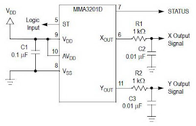 |
| Accelerator sensor with MMA 3201 |
Feature Sensor Accelerometer MMA 3201
- Sensitivity in two separate axes: 40g X-axis and 40g Y-axis
- Integral Signal Conditioning
- Linear Output
- Ratiometric Performance
- 4th Order Bessel Filter Preserves Pulse Shape Integrity
- Calibrated Self-test
- Low Voltage Detect, Clock Monitor, and EPROM Parity Check status
- Transducer Hermetically Sealed at Wafer Level for Superior Reliability
- Robust Design, High Shocks Survivability
LM389 low power audio amplifier
Amplifier circuit below represents a very small amplifier circuit output. Maximum output is no more than 1W, comprehension is low but received a series of sensitive enough, and power amplifier circuit is very suitable for use in radio receiver, especially on FM radio.

Minimum Voltage = 4 Volt DC
Maximum Voltage = 15 Volt DC
Power Output = 0,325 W
RL = 8 Ohm
Ft = 40Hz - 18KHz
Icco = 6mA
Part List :
R1 = 100K
R2 = 2,7R
R3 = 1K
C1 = 100uF
C2 = 220uF
C3 = 47uF
C4 = 0,01uF
Wednesday, October 30, 2013
Simple accu charger circuit

Accu charger circuit is very simple and easy to make, because it only requires a few components are also not more than 10 components. Besides easy charger circuit is also very cheap and very efficient.
This circuit requires power supply from a transformer that comes from an AC voltage 220 and diuturunkan be 12-13 volts and then enter to-circuit and 12 Volt DC output allows for charging 12V battery
| Simple charger schematics |
Professional Installation of Auto Sound Systems Imperative
One of the biggest decisions that people need to make when deciding on an auto sound system is the decision of whether or not have the system professionally installed. On the one hand, it will add a pretty hefty fee to the bottom line but you just might find that the fee is well worth the expense youd have to pay to fix any mistakes you might make along the way. The truth of the matter is that installing an auto sound system is not an easy task and requires no small degree of skill and concentration. Im not sure about you but Im in short supply of both when it comes to technical matters such as this and would much rather not risk my car, which will cost a lot more to repair if I make a mistake than the couple of hundred dollars that professional installation might require.
When it comes down to it there are many benefits to having your sound system installed by professionals. Below you will find a few of these benefits.
1) Sound systems are huge investments. Most automobiles come equipped with a marginal sound system at best. Many people will spend hundreds if not thousands of dollars on upgraded materials for sound systems but then skimp on installation. The result is a sound system that is very unlikely to provide the actual quality you paid for. Professionals train for months, even years, in order to learn how to properly place and install each component in order to achieve the best possible sound inside your automobile. If you do not have the training you cannot possibly expect the same results. Protect your investment by making the extra investment of a professional installation.
2) Saving money in costly repairs. This is especially important when installing in dash auto sound systems. You will be pulling out pieces and parts and may even need to make adjustments to the available space in order to get a new sound system to fit in the space allotted for a sound system in your automobile. Professionals not only have the skills to handle these types of adjustments without damaging your dash or automobile but also the tools that might make the difference between making a tiny adjustment and a huge mess. Dont risk the need to pay for factory repairs from your carmaker to fix the mess youve made of your automobile.
3) Sound systems arent cheap. For this reason alone you need to make sure you arent putting your brand new sound system at risk by foolishly attempting the installation for yourself. Even if you purchase the extended warranty on your system you may find that the warranty is void if you did not have a professional installation performed. If you have a professional installation the warranty is generally in tact if problems are found with your equipment during the installation process. In other words, having a professional installation is another layer of security for your investment.
4) Someone else is responsible for goof ups. This is probably the best reason on earth to spend the extra money on a professional installation. If something goes wrong during the process, it is someone elses fault and you do not have yourself to blame. Even better than that, someone else is responsible for fixing the mistake and covering the cost of any damage that may have occurred. This reason is enough for me to add another hundred or so dollars to my investment and take the time to have a professional installation. If something goes wrong on a thousand dollar piece of equipment or a thirty plus thousand dollar automobile, I want someone other than myself to yell at. But hey, thats just me.
Sound systems greatly affect how much we enjoy our time in our cars, trucks, and SUVs it only makes sense to get the best sound system we can afford to improve the quality of the time we spend in our automobiles. Dont ruin the investment by skimping on the installation, it could cost more in the long run than you realize at the time of the purchase.
TFDS4500 Infrared Adapter Serial Transceiver
This electronic infrared adapter serial transceiver circuit is based on a TFDS4500 IC and can be used to transmit data from portable devices to a PC using IR and serial port .
Infrared Adapter Serial Transceiver Schematic

TFD4500 infrared adapter it’s a low–power infrared transceiver modules for serial infrared (SIR) data communication which support IrDA speeds up to 115.2 kbit/s. In this infrared circuit transceiver it’s integrated an photo diode infrared emitter (IRED) and a low–power analog control IC.
Tuesday, October 29, 2013
50W AF Power Amplifier with STK4036II Schematic Circuit
 50W AF Power Amplifier with STK4036II Schematic Circuit
• Compact package for thin-type audio sets
• Member of pin-compatible series with outputs of 20 to 200W
• Easy heatsink design to disperse heat generated in thintype stereo sets
• Constant-current circuit to reduce supply switch-on and switch-off shock noise• External supply switch-on and switch-off shock noise muting, load short-circuit protection, thermal shutdown and other circuits can be tailor-designed.
Metal Detector Schematic Using CS209A
A very simple metal detector electronic project circuit can be designed using the CS209A integrated circuit manufactured by Cherry Semiconductor.The CS209A integrated circuit is a bipolar monolithic integrated circuit for use in metal detection proximity sensing applications.The CS209A metal detector contains two on-chip current regulators, oscillator and low-level feedback circuitry, peak detection/demodulation circuit, a comparator and two complementary output stages.The oscillator, along with an external LC network, provides controlled oscillations where amplitude is highly dependent on the Q of the LC tank.
Metal Detector Schematic Circuit Diagram

The detector, is a single 100uH coil. The IC has an integral oscillator the choke forms part of an external LC circuit, its inductance being changed by the proximity of metal objects. It is the change in oscillation that is amplified and demodulated. Led 1 will light and the buzzer will sound when the inductance its changed. Set up is easy : R5 is adjusted with the LC away from any metal source so that the LED lights and buzzer sounds. The control is backed off so that the LED goes out and buzzer stops. When the choke comes into contact with any metal object that alters its inductance, LED 1 and the buzzer will activate.
FOr this electronic project youll need the following electronic parts: R1=220ohms, R2,R5=10k,R3=1k ,C1,C3=2.2nF; C2=10uF. Entire circuit can be powered from a 9 volts battery.
Metal Detector Schematic Circuit Diagram
FOr this electronic project youll need the following electronic parts: R1=220ohms, R2,R5=10k,R3=1k ,C1,C3=2.2nF; C2=10uF. Entire circuit can be powered from a 9 volts battery.
Basic Automatic Day Night Lamp with LDR
Automatic Day-Night Lamp wit LDR

Maybe its a lot who know how to work this one series, but I wanted to share back to the beginner on this. In the existing lighting circuit automatic lights that use components LDR (Light Dependence Resistor).
The workings of LDR LDR is exposed to light if the layer of the resistance was weakened likewise if there is no light at all resistance enlarged. here could make friends like that, because its components are a little easy but we will use the 220V AC voltage of course you must be very careful. Rather than actually being burnt. The author asks to be careful for the beginner course.
Read More..
Maybe its a lot who know how to work this one series, but I wanted to share back to the beginner on this. In the existing lighting circuit automatic lights that use components LDR (Light Dependence Resistor).
The workings of LDR LDR is exposed to light if the layer of the resistance was weakened likewise if there is no light at all resistance enlarged. here could make friends like that, because its components are a little easy but we will use the 220V AC voltage of course you must be very careful. Rather than actually being burnt. The author asks to be careful for the beginner course.
 |
| Schematic LDR |
LDR components can be interconnected with a cable, so tools stay in the house but LDR is outside the home. It is recommended using qualified Relay no1 to avoid fire, because the relays are cheap to produce heat. Relay that cheap is not in use for high voltage. Travonya use the cheap, because this circuit does not require large currents. The function of Potensio 500KΩ to regulate Q1 & Q2 is on, if both the active transistor relay also participate actively.
Monday, October 28, 2013
AMN12111 PIR Motion Sensor

PIR movement sensor module (Passive Infra Red) motion detection sensor AMN12111 is the smallest of objects the size of its shape. PIR motion sensor module (Passive Infra Red) AMN12111 fresneal come equipped with a lens. PIR motion sensor module (Passive Infra Red) AMN12111 has advantages can be directly connected to the microcontroller or other actuator driver.
PIR movement sensor module (Passive Infra Red) AMN12111 has a sensitivity that is very sensitive to changes in motion around it. PIR movement sensor module (Passive Infra Red) AMN12111 very suitable when applied to security systems. The price of the PIR movement sensor module (Passive Infra Red) AMN12111 not quite expensive. readily available in the market. For those of you who want to make a motion detection sensor. PIR movement sensor module (Passive Infra Red) AMN12111 is much easier and more practical than you have to make a series of Infra Red with the Tx and Rx.
Flip Flop Led Circuit
Flip Flop LED
Flip flop circuit is a series of free runing multivibrator given the burden of LEDs on each side of the transition changes its output signal. Flip flop circuit with LEDs is quite simple, that is prepared with 2 units and 2 units of 2N3904 transistor circuit tank circuit composed by the RC circuit.
LED indicators signal a change that is placed on each side of the flip flop will be lit in turn by the fire and extinguished the same as the charge and discharge capacitor. Flip flop circuit is quite simple as shown in the picture below.Flip Flop LED series

The working principle is the flip flop over when the series voltage source is given then the 10uF capacitor will be charged through R 470 and the LED will then be forwarded to triger the transistor base so that the transistor will turn ON and LEDs. this occurs alternately on each side, so that the LED light will illuminate in turn as well.
Simple power saver circuit
This circuit is used to save electricity in our homes to avoid spending too much . How it works ? This circuit of works to filter the AC voltage , and reduce the magnitude of the cosine curve AC current that will be read on the instrument KWH meters. KWH meters will work if there is a load wire passing through a coil of wire sensors to measure the AC current is passed, if the current through a lot of electricity. C1 and C2 worked as a deduction from stamping voltage if the switch is connected, so that equipment or components which enter the voltage was not much shocking.
Part List :
C1,C2 = 100pF / 400V or higher
C3 = 10uF / 400V non polar capacitor
Fuse = 0.5W
S1 = Switch on/off
Use best quality capacitors

Use the circuit on each item that requires AC power house to besaved using voltage field of electronics goods. Or if you take the trouble to make on each item , then use immediately near the KWH meter, to disconnect to tke their input and issued again on output, should use the box to close the circuit.
I got this Idea from this useful site here
Sunday, October 27, 2013
Protectors Circuit on SMPS power supply
The simplest example SMPS which still uses 3 transistors (C3807, A1015 and power transistors) classic problem that often occurs is: - Problem in the feedback circuit can cause the output voltage B + over so that it can endanger the aircraft as a whole. For example elco erupted, pcb burnt burnt by over-heated, horizontal transistor short.
- Problem on feedback circuits may cause power regulator transistor is damaged due to over current transistor (eg, due to the 47k resistor transistor circuit on the secondary error detector value is delayed).
- If the input ac voltage drops can cause the power regulator transistor is damaged, due to over current transistor If the secondary there is a power transistor short can cause damage over current regulator.
- Protectors are designed to make the SMPS SMPS "reliable will not be damaged" if there are things that go wrong as mentioned above.
 |
| SMPS Circuit |
SMPS circuit using IC systems generally are designed with a surge protector, which include:
- Over voltage protector (OVP)
- Over current protector (OCP)
- Over load protector
- Short circuit protector
- Over temperature protector
2x6W Stereo Audio Amplifier based LA4440 Power IC
This is the diagram of 2x6W stereo audio amplifier based LA4440 power IC. Actually, the LA4440 can be used in both stereo mode and mono (bridge) mode, but the circuit presented in this post is LA4440 in stereo mode. The recommended power supply is 13.2V, while the maximum voltage rated at 18V.

LA4440 Features:
- Built-in 2 channels (dual) enabling use in stereo and bridge amplifier applications.
- Dual : 6W´2 (typ.)
- Bridge : 19W (typ.)
- Minimum number of external parts required.
- Small pop noise at the time of power supply ON/OFF and good starting balance.
- Good channel separation.
- Good ripple rejection : 46dB (typ.)
- Low distortion over a wide range from low frequencies to high frequencies.
- Small residual noise (Rg=0).
- Easy to design radiator fin.
- Built-in protectors.
- Built-in audio muting function.
- Thermal protector
- Overvoltage, surge voltage protector
- Pin-to-pin short protector
Coil Coupled Operation Metal Detector
A Coil Coupled Operation Metal Detector made from readily obtainable components and using an ordinary medium receiver as a detector.
Coil Coupled Operation Metal Detector Circuit Diagram

Notes:
The metal detector shown here may well represent a new genre. At any rate, after some exposure, it is regarded as such by those who have seen it. It is based on a standard transformer coupled oscillator (TCO) hence the name Coil Coupled Operation (CCO) Metal Detector. Although requiring a BFO (in this case provided by a Medium Wave radio), it differs from a typical BFO detector in that its performance far outstrips that of BFO. Also, unlike BFO, it is dependent on the balance of two coils to boost sensitivity. It also differs from IB, in that its Rx section is an active, rather than passive, component of the oscillator. Further, unlike IB, the design does not require critical placement of the coils. As with both BFO and IB, the design provides discrimination. Experiments with different embodiments of the idea have shown that it has the potential to match the best of IB. Happy hunting!
Coil Coupled Operation Metal Detector Circuit Diagram
The metal detector shown here may well represent a new genre. At any rate, after some exposure, it is regarded as such by those who have seen it. It is based on a standard transformer coupled oscillator (TCO) hence the name Coil Coupled Operation (CCO) Metal Detector. Although requiring a BFO (in this case provided by a Medium Wave radio), it differs from a typical BFO detector in that its performance far outstrips that of BFO. Also, unlike BFO, it is dependent on the balance of two coils to boost sensitivity. It also differs from IB, in that its Rx section is an active, rather than passive, component of the oscillator. Further, unlike IB, the design does not require critical placement of the coils. As with both BFO and IB, the design provides discrimination. Experiments with different embodiments of the idea have shown that it has the potential to match the best of IB. Happy hunting!
Saturday, October 26, 2013
Surround Amplifier Circuit with TDA7053
Surround Amplifier Circuit with TDA7053

Read More..
Perhaps the surround amplifier circuit below is an interesting circuit is made. For, making easy just by using the IC and electrolytic capacitor added 1 , we already can hear the strains of music with sound ( Front Left ,Right and surround Right , Left. In addition to listening to music , this amplifier is also very suitable for gamers who want good sound quality.
Minimum voltage requred 9 volts and maximum of 15 volts. Power Output of each speaker 10 Watt with 4 ohm impedance.
Lithium ion Charger Using MAX8844
Using the MAX8844 lithium ion charger IC released by Maxim Semiconductors you can design an very simple and efficiency charger circuit for charging a single cell lithium-ion battery . The MAX8844 lithium ion charger integrate a current-sense circuit, MOSFET pass element, thermal-regulation circuitry, and eliminate the external reverse-blocking Schottky diode to create the simplest and smallest charging solutions for handheld equipment.
Lithium ion Charger Circuit diagram

Also , using this charger solution the power source is optimized by the MAX8844Z using automatically select function between the USB or IN power source but if are both power sources connected the highest priority is for IN power source to ensure the shortest charging time for the system . The MAX8844 charger chip accept an input voltages range from 4.25V to 28V (IN and USB), but the charging is disabled if the input voltage exceeds +7.5V for protection against unqualified or faulty AC adapters.
These charger IC is very easy to be implemented in applications like : Bluetooth Equipment , Cellular and Cordless Phones Charging Cradles and Docks, Digital Still Cameras , MP3 Players Smart Phones and PDAs , USB Appliances . The maximum charging current is programmed by an external resistor connected from SETI to GND (RSETI). Use the following equation to determine the fast-charge current (IFAST-CHARGE): FAST CHARGE= 1250V/RSETI, where IFAST-CHARGE is in amps and RSETI is in ohms. RSETI must always be 1.25k or higher due to the continuous charging current limit of 1ARMS.
Lithium ion Charger Circuit diagram
These charger IC is very easy to be implemented in applications like : Bluetooth Equipment , Cellular and Cordless Phones Charging Cradles and Docks, Digital Still Cameras , MP3 Players Smart Phones and PDAs , USB Appliances . The maximum charging current is programmed by an external resistor connected from SETI to GND (RSETI). Use the following equation to determine the fast-charge current (IFAST-CHARGE): FAST CHARGE= 1250V/RSETI, where IFAST-CHARGE is in amps and RSETI is in ohms. RSETI must always be 1.25k or higher due to the continuous charging current limit of 1ARMS.
Schematic Audio Amplifier Circuit 200W

Load Resistance : 8ohms
Input impedance : 55K
Maximum supply voltage : (+95v)-0-(-95v)
Recommended supply voltage : (+66v)-0-(-66v)
This complete aerial quality, low babble address audio ability amplifier is based about the Hybrid Integrated Ambit STK4050 bogus by Sanyo. The ambit incorporates aggregate and has a best music achievement ability of 200W.The ambit incorporates an on lath ability supply; therefore, alone centre broke agent is appropriate to ability the circuit. I t has actual acceptable affection sound. U can use it with your Home Theatre your PC & etc... You can additionally use it as Subwoofer Amplifier.
It is a bunched amalgamation for THIN-TYPE Audio sets. Easy Heatsink architecture to banish calefaction generated in THIN-TYPE audio sets. Constant-Current ambit to Reduce accumulation switch-ON and switch-OFF shock noise. External accumulation switch-On and switch-OFF shock babble muting, Load circumlocute protection, thermal abeyance and added circuits can be tailored-designed.
Friday, October 25, 2013
Multiplexer with CMOS IC 4556
In addition to the family of TTL ICs that support the function of a multiplexer is a family of CMOS ICs.

Read More..
Despite the fact it is the family of TTL ICs that support more functions than the CMOS multiplexer. For the working principle of the multiplexer IC CMOS family is actually tantamount to a multiplexer circuit, or IC TTL logic gates. That should be all referring to the real multiplexer function, namely the determination of output lines which represent the number of input lines. The use of symbols is possible between TTL and CMOS IC has a different but actually run the same rules. For your reference if you are interested in using family of CMOS IC 4556 series in particular, I include also the truth table below:
INPUT | OUTPUT | |||||
E | A0 | A1 | O0 | O1 | O2 | O3 |
L | L | L | L | H | H | H |
L | H | L | H | L | H | H |
L | L | H | H | H | L | H |
L | H | H | H | H | H | L |
H | X | X | H | H | H | H |
L = LOW | ||||||
H = HIGH | ||||||
Differences subwoofer and woofer speakers
In the world of electronics, especially in terms of audio must be familiar with the term speaker, be it a woofer or subwoofer. Each of these types of speakers choose a variety of characteristics and differences. Here will be explained a little about subwoofe speakers and woofer speakers, so we can find out where the fine for use as needed.
 |
| Subwoofer Speaker |
Subwoofer is a bass speaker system yangg could produce a lower frequency than usual with an additional woofer low pass filter.Walaupun sub-woofer does not have to wear two opposite poles mounted speakers, a good sub-woofer is that using 2 woofers for the volume remains loud. Sub woofer with the woofer does not always have a special, because ordinary woofer can be built into the subwoofer, by adding an amplifier low pass filter. Sound system (sound system) even if only to include a sophisticated subwoofer, along with some other speakers.
And in other words, the difference in bass speaker (woofer) with speaker Sub Woofer:By description SUB word, it means the speaker must be able to handle bass tones below.
Bass speakers can use the speakers with her without a rubber edge cones.
Speaker Sub Woofer, using cones with rubber edges, so its more flexible movement of cones.
Performance of all speakers (tweeter, Middle, woofer or sub woofer) strongly depends on the source signal and Pre Amp and Power of his amps. So if not supported by all three of these factors, it will not produce a good tone (tone control).
Regarding his Ohm, 100%, depending on its output amps.
Like the amps in the car, the output is 4 ohms, while the home is generally 8 ohm amp, but there is also a distinguished 16 ohms. So adjust the speakers to the amplifier.
So the key difference lies in the low tones (bass) are produced. Subwoofers capable of producing a low tone below the average normal woofers, and the tone is also more melodic and soft . So what can I share, may be useful to visitors all. Thank you
Accu charger with IC LM723C
Circuit of 12 V accu / battery charger with IC LM723C. This Accu charger have input from the first transformer - voltage 220 initially V/110V/240V, the input voltage lowered approximately 12 VAC, then voltage 12 Volts will be rectified by D1 and then filtered by C1 , then filtered and amplified again by IC LM723 and NPN transistor , output voltage is ready to use to charging the accu / battery.
 |
| Accu charger with IC LM723C |
T1 = Transformer , DC 12 V
D1 = Diode bridge
C1 = 470uF /50V
C2 = 1000pF
R1 = 4R7
R2 = 5K
R3 = 3K9
R4 = 7K5
R5 = 8K2
VR = 2K - 5K trim
TR1 = MJ2840
IC = LM723C
Thursday, October 24, 2013
Electronically Designed Siren
The circuit was designed to create an electronic siren to provide a scheme for producing an alert sound in emergency cases or any circumstances that requires its usage.
Electronically Designed Siren Circuit Diagram

The voltage used by capacitor C3 is used to regulate the VCO of IC3 which is a phase-locked loop logic IC. This enables one output to be a modified audio. The sound of the siren can be altered by changing the values of the resistors and capacitors that will include some experimentation to adjust the sound. The duration and time of operation of operation is determined by the combination of R1 and C1 while the frequency of the produced sound is handled by the combination of R4 and C2. Lastly, the changing of sound is controlled the R3 and C3 combination.
The electronic siren system is ideally used in warning equipments in the field of police vehicles such as cars and motorcycles, ambulances, fire trucks or engines, and other types of emergency vehicles. When used on stationary places, there are more effective in security & protection, home alarm, water alarm, and public alert systems which provide alarming sound to municipalities and cities, in establishments like plants, factories and locations with potentially dangerous materials. They are also utilized in open spaces, halls and arenas. The most important feature that they provide is in cases of emergency situations in which they are being used for large warning systems. In choosing an electronic siren, the features such as light weight, high intensity shell, high reliability, and good quality with excellent workmanship, should be considered.
- 4011 – a quad 2-input NAND gate integrated circuit, generally characterized by small fluctuation in voltage supply, very high impedance, outputs that can sink and source, one output can drive up to 50 inputs, high speed gate propagation time, high frequency, and low power consumption.
- 4066 – a digitally controlled quad analog switch utilizing advanced silicon-gate CMOS technology with features such as individual switch controls, matched switch characteristics, pin and function compatibility, low quiescent current, low ON resistance, wide analog input voltage range, and 15 ns typical switch enable time.
- 4046 – a phase locked loop CMOS logic IC used in motor speed control, FSK modulation, tone decoding, voltage-to-frequency conversion, data conditioning and synchronization, frequency discrimination, frequency multiplication and synthesis, and FM modulator and demodulator, due to its high VCO linearity, low frequency drift, low dynamic power consumption, and wide supply voltage range.
Electronically Designed Siren Circuit Diagram
The voltage used by capacitor C3 is used to regulate the VCO of IC3 which is a phase-locked loop logic IC. This enables one output to be a modified audio. The sound of the siren can be altered by changing the values of the resistors and capacitors that will include some experimentation to adjust the sound. The duration and time of operation of operation is determined by the combination of R1 and C1 while the frequency of the produced sound is handled by the combination of R4 and C2. Lastly, the changing of sound is controlled the R3 and C3 combination.
The electronic siren system is ideally used in warning equipments in the field of police vehicles such as cars and motorcycles, ambulances, fire trucks or engines, and other types of emergency vehicles. When used on stationary places, there are more effective in security & protection, home alarm, water alarm, and public alert systems which provide alarming sound to municipalities and cities, in establishments like plants, factories and locations with potentially dangerous materials. They are also utilized in open spaces, halls and arenas. The most important feature that they provide is in cases of emergency situations in which they are being used for large warning systems. In choosing an electronic siren, the features such as light weight, high intensity shell, high reliability, and good quality with excellent workmanship, should be considered.
Differences subwoofer and woofer speakers
In the world of electronics, especially in terms of audio must be familiar with the term speaker, be it a woofer or subwoofer. Each of these types of speakers choose a variety of characteristics and differences. Here will be explained a little about subwoofe speakers and woofer speakers, so we can find out where the fine for use as needed.
|
| Subwoofer Speaker |
Subwoofer is a bass speaker system yangg could produce a lower frequency than usual with an additional woofer low pass filter.Walaupun sub-woofer does not have to wear two opposite poles mounted speakers, a good sub-woofer is that using 2 woofers for the volume remains loud. Sub woofer with the woofer does not always have a special, because ordinary woofer can be built into the subwoofer, by adding an amplifier low pass filter. Sound system (sound system) even if only to include a sophisticated subwoofer, along with some other speakers.
And in other words, the difference in bass speaker (woofer) with speaker Sub Woofer:By description SUB word, it means the speaker must be able to handle bass tones below.
Bass speakers can use the speakers with her without a rubber edge cones.
Speaker Sub Woofer, using cones with rubber edges, so its more flexible movement of cones.
Performance of all speakers (tweeter, Middle, woofer or sub woofer) strongly depends on the source signal and Pre Amp and Power of his amps. So if not supported by all three of these factors, it will not produce a good tone (tone control).
Regarding his Ohm, 100%, depending on its output amps.
Like the amps in the car, the output is 4 ohms, while the home is generally 8 ohm amp, but there is also a distinguished 16 ohms. So adjust the speakers to the amplifier.
So the key difference lies in the low tones (bass) are produced. Subwoofers capable of producing a low tone below the average normal woofers, and the tone is also more melodic and soft . So what can I share, may be useful to visitors all. Thank you
TBA820 low power audio amplifier

At this time amplifier circuit based on IC KA2201, TBA820M, LM820M, and U820. You can use all ic is the series under the scheme. This amplifier circuit has a very small output power or low at 2W. Required supply voltage from 3 volts to a maximum of 16 volts.
Below is a scheme of this power amplifier

Part List
R1 = 100K
R2 = 120R
R3 = 100R
C1 = 100nF
C2 = 100uFC3 = 470uF
C4 = 220pF
C5 = 47uF
C6 = 100uF
IC = KA2201 , LM820M , TBA820M , U820MWednesday, October 23, 2013
LM556 Flip Flop Truth Table
The circuit on this piece of paper is on behalf of a hybrid - traditional / RESET type of logic Flip-droop so as to is constructed from an LM556 - Dual Timer integrated circuit.
 |
| LM556 Flip-Flop Truth Table |
The design is crude but helpful for very low hustle applications. Its maximum asset is so as to the outputs of the LM556 are skillful of driving current oodles of up to 200 milliamps with a minimum voltage loss.
This circuit was originally residential to drive “Stall Motor” type switch tackle with the aim of are used on replica railroads. These motors practice low voltage DC and pass approximately 15 milliamps whilst they are happening a held up condition.
Due to the design of the LM556 timer counter in attendance are multiple output options unfilled in this design. These include the conventional timer outputs which are bipolar and the ‘DISCHARGE’ terminals, (PINS 1 and 13), with the purpose of are approachable antenna circuits.
source:http://home.cogeco.ca/~rpaisley4/LM555.html#12
Touch Switch using NE555
The series of touch switch or touch switch is built by IC NE555, a series of touch switches can be used to turn on lights, alarms or other electronic equipment.
This circuit uses 2 pieces of metal plate media as touch, MP1 (Metal Plate 1) and MP2 (Metal Plate 2). Touch switch circuit is equipped with a visual LED indicator for relay status (load active). To enable (Relay ON) can be done by touching the surface of MP1 and to turn it off by touching the surface of the MP2. MP1 and MP2 in touch this switch can use a small piece of copper (diameter 5mm) was enough.
This circuit uses 2 pieces of metal plate media as touch, MP1 (Metal Plate 1) and MP2 (Metal Plate 2). Touch switch circuit is equipped with a visual LED indicator for relay status (load active). To enable (Relay ON) can be done by touching the surface of MP1 and to turn it off by touching the surface of the MP2. MP1 and MP2 in touch this switch can use a small piece of copper (diameter 5mm) was enough.
Touch Switch series with NE555.

Component List 555 touch Switch
R1 = 3.3M
R2 = 3.3M
R3 = 10K
R4 = 1K
C1 = 10nF-63V
D1 = 1N4007
D2 = Red LED
Q1 = BC547
IC1 = NE555
RL1 = 12V Relay
Different types of TV TUNER
TV tuner that is used on older models and new models of television there are some differences. Therefore, understanding the different types of tuner would be useful if we want to replace the tuner with the other models.
Supply voltage tuner.
Tuner older models generally use a supply voltage of 12v, the new models are commonly used 5V supply voltage. Some use a 9V voltage, but very rare.
 |
| TV TUNER |
Voltage Synthesizer tuner (VS tuner)
Tuner that uses a tuning control (VT or BT) with a voltage between 0 to 33V Voltage Synthesizer tuner named. TV can be found on the aircraft models, old and new
Based on how the control band-switch, Tuner VS then there are 2 kinds, namely
Using 3-Band input sw, the VL-VH-U
Using 2-Band input sw, the Band SW1 and SW2 Band. This tuner is actually similar to the type of band 3-sw. For control-sw 2 band is in the tuner will still be converted into 3-sw bands.
Frequency Synthesizer tuner (FS tuner) or the type of PLL
Tuner wherein the tuning voltage and the voltage controlled band switching the digital communication through SDA and SCL. This tuner has a supply voltage Vcc, which is
5V is used for the digital tuner circuit control and
33V (fixed voltage or fixed) is used to control the voltage supplied to the tuning in the digital circuits within the tuner.
(Tuner old) sometimes there are additional circuit voltage of 12V to the tuner.
Frequency band.
Based on the wide range of revenue-frequency band, there are three kinds of tuner
Normal tuner
Superband tuner
Tuner hyperband
Normal tuner, the tuner that can receive broadcasts "on-air" (terrestrial) TV in the frequency band:
- Frequency of VHF Band I - VL 41-68 Mhz
- Band III - VH 174-230 Mhz
- Frequency UHF Band IV - U 470-581 Mhz
- Band V - U 582-960 Mhz
- Band II 87.5 - 104 MHz is used for FM radio broadcasting
- VL and VH bands used for broadcast channels 2 through 12
- U bands used for broadcast channels 21 to 69
Superband Tuner and Hyperband, the tuner can receive broadcast as normal tuner plus the ability to receive broadcasts "off air" CATV (cable television).
- S band using frequency band between VL and VH
- H-band using a frequency band between VH and U
- Superband Tuner can receive the broadcast band S
- Hyperband tuner can receive broadcast band and S band H
Based on the IF frequency out
IF frequency tuner out there who have 38/38.9/45.75 Mhz frequency. In Indonesia generally use 38.9Mhz frequency, but sometimes there is a use 38.0Mhz
Based on the pin-out
There are several kinds of tuner long pin-out configuration. But now almost all the tuner is already using an international standard 11-pin
Universal tuner
China is now producing "universal tuner" 11-pin. Indonesia was just the market we do not know whether it exists or not. This tuner can be used to substitute for the various types of tuners and tuner can adjust to this direct voltage of 5, 9, or 12v.
RF antenna input connector
Form the antenna input connector there are two kinds, namely:
- RCA type connectors
- Antenna RF connector
Tuner modules
Tuner is a tuner module inside there are all Video IF amplifier circuit and the FM-detector. This kind of tuner is using VS and some are using the FS.
Tuner module has output like:
- RF AGC-out
- RF AFC-out
- Audio-out
- Video-out
- Base band out, the signal to be processed into stereo sound circuit.
Except that in tuner is also sometimes diperlengkapa with audio-switch to TV / AV-in. Therefore, to the sound of the AV-in connected via Audio-in found on the tuner module. Sometimes the sound volume to be controlled in the tuner module.
- SONY tuner module 1
- SONY tuner module 2
- Toshiba tuner module
Impedance input / output
Impedance tuner has all kinds of input / output 75 ohm.
How to distinguish 2-band tuners VS sw with PLL tuner FS
In all these circumstances and the removable pin 11 feet was not cut, it is sometimes difficult to distinguish between two band-tuner tuner sw with FS.
Some models have a tuner pin legs partially emptied. FS Tuner has a location pin 30V voltage 3 numbers from the back (of the IF pin out).
Tuesday, October 22, 2013
High voltage inverter circuit diagram

This inverter circuit works with a transistor and transformer and other components to increase the voltage becomes high. Input supply voltage ranging from 3V to 6V DC, later it was raised to high voltage AC. However, in this inverter circuit output current is very small, probably under 0.1A even smaller. However, its use you can apply it on a fluorescent lamp 10W maximum power only, and that too takes time to switch on fluorescent lamps.Part List
R1 = 4K7
R2 = 2K2
R3 = 330K
C1 = 100nF
C2 = 100nF 275V
C3 = 0.22uF 275V
Q1 = D506
L1 = 100 times winding, with 0.8mm diameter copper wire
L2 = 50 times winding, with 0.8mm diameter copper wire
L3 = 5000 times winding, with 0.4mm diameter copper wire
High efficiency stereo Class D audio amplifier
The SSM2380 is a fully integrated, high efficiency, stereo Class-D audio amplifier designed for mobile phone applications , mp3 players and other audio applications that require low output power . This class D audio amplifier circuit requires few external components and operates from a single 2.5 V to 5.5 V supply.
SSM2380 audio amplifier circuit is capable of delivering 2 W of continuous output power with <1% THD + N driving a 4 ohms load from a 5.0 V supply, or 1.4 watts of continuous output power on a 8 ohms load .
The SSM2380 features a highly flexible I2C interface with many useful settings. Using the I2C control interface, the gain of SSM2380 can be selected from 1dB to 24 dB + Mute in 47 steps with no external components Other features accessed from the I2C interface are: independent L/R channel shutdown, variable ultra-low EMI emission control mode, Automatic Level Control (ALC) for high quality speaker protection, and Stereo-to-Mono mixing operation.
The SSM2380 features a high efficiency, low noise modulation scheme that requires no external LC output filters.

It operates with 93% efficiency at 1.4 W into 8 ohms or 85% efficiency at 2W into 4 ohms from a 5.0 V supply and has an SNR of >100 dB.
Main features of the SSM2380 audio amplifier are : highly configurable I2C interface , stereo amplifier configuration , stereo-to-mono mixer option via I2C control , 93% efficiency at 5.0 V, 1.4 W into 8 ohms speaker , >100 dB signal-to-noise ratio (SNR) , single-supply operation from 2.5 V to 5.5 V , 20 nA ultralow shutdown current , short-circuit and thermal protection , pop-and-click suppression.
12V SCR Battery Charger
This battery charger circuit differs from the norm in a number of ways, all of which make it difficult to understand. For this reason, I do not recommend it for the beginner.
Repairing /revamping a dead charger
What I started with was an inoperative 12amp battery charger. In hope of repairing it, I traced out the circuit, but did not like what I found—poor circuit design. So what I had to start with was an enclosure, ammeter, thermal overload interrupter, and center-tapped transformer all designed for battery charger application. Since the maximum current delivered by the unit is a function of the transformer internal impedance, I recommend that the readers use the same type of transformer. If you are a good pack-rat (like me), you may already have a dead charger—or you can be on the lookout for one.
12V Battery Charger Schematic

SCR (Thyristor) Rectifiers
First of all, the two SCRs (silicon controlled rectifiers or thyristors) are connected with their anodes (stud or tab) grounded—this makes for excellent thermal transfer because no insulating hardware is required (if it is permissible to connect the negative terminal of the charger directly to the steel enclosure). If you do not wish to ground this point, use insulating hardware to electrically isolate the SCRs. This makes the transformer center-tap the positive terminal. The reason for this circuit placement is the ease of driving the SCR gates via the positive battery voltage—it is very unconventional as I have never seen this trick done before.
SCRs are the ideal power device choice for a battery charger because they can both regulate battery charging voltage and prevent fault current when the battery is inadvertently connected reverse. I have actually connected mine reverse and thought that the charger was inoperative until I realized what I had done.
Power Device Selection
I used two 2N690 stud-mount SCRs that I had available. Any in the series will work (2N683 through 2N690)—only the voltage rating differs and anything greater than 100V is good for the application. Other more inexpensive TO-220 candidates are: STMicroelectronics TYN616, Teccor/Littlefuse S6015L (isolated package), NXP 151-500C, or ON Seimconductor 2N6403G. Avoid sensitive gate devices.
Circuit Common
Normally circuits use a negative common—that is just the way the world seems to work, but in this case, it was more convenient to make the positive rail the common point and all visualization must be made with this in mind. The only exception is D7 that was installed to prevent damage should the battery get connected reverse. For visualization, simply short out D7. The conventional ground symbol is used for the negative rail. This tends to tie your brain in knots…
Voltage Reference
A good battery charger tapers off when the battery voltage is above about 14V. For this to function, D6 is a 5.1V shunt zener regulator that puts out -5.1V relative to the positive rail. It is biased via R8.
Ramp Generator
C1 and R4 form a ramp generator that generates a negative going sawtooth voltage (relative to the positive rail). It is reset to the positive rail via Q1 and Q2 at line voltage zero crossing. At zero crossing, there is no voltage at the anodes of D3 & D4 (relative to the positive rail), Q1 is off, Q2 is on and C1 is shorted. At all other points in the AC line cycle, C1 is charging. My line frequency is 60HZ. For 50HZ, increase the value of R4 to 82K.
Error Amplifier
U1A is the error amplifier—it amplifies the difference between the -5.1V reference voltage and the feedback voltage at the arm of the V ADJ pot (R6). It is slowed down by the RC filter (R10 & C2), proportionately amplified by the ratio of R14 /R9, and integrated via C3. Perhaps you have heard of a PID (proportional, integral, derivative) control—this does just that, but neglects the derivative term as it is generally not required in most applications. If the error amplifier is not satisfied, it continues to integrate its output voltage until the feedback voltage equals the reference voltage. The function of the operational amplifier is to make the two input voltages equal.
The device selection here is the LF442 (or TL082) J-FET input operational amplifier. This is vital in this circuit because the common mode voltage range of the differential inputs must extend to the positive rail. Few op amps can do this (many have differential voltages that extend to the negative rail, but those will not work in this application).
Phase Comparator
U1B is the phase comparator. It compares the ramp voltage with the output of the error amplifier. It is also called the ramp-intercept technique. When the ramp generator voltage exceeds the error voltage signal (in the negative direction), the output of U1B switches negative and turns on Q3 thus providing gate current to the SCR that is forward biased. R13 is the gate current limiting resistor.
Flashing a Dead Battery
The battery provides the power to begin operation of the regulator circuit, so if the battery is fully discharged it may be necessary to “flash” the battery terminals with a good battery to bootstrap the regulator into operation.
Repairing /revamping a dead charger
What I started with was an inoperative 12amp battery charger. In hope of repairing it, I traced out the circuit, but did not like what I found—poor circuit design. So what I had to start with was an enclosure, ammeter, thermal overload interrupter, and center-tapped transformer all designed for battery charger application. Since the maximum current delivered by the unit is a function of the transformer internal impedance, I recommend that the readers use the same type of transformer. If you are a good pack-rat (like me), you may already have a dead charger—or you can be on the lookout for one.
12V Battery Charger Schematic
SCR (Thyristor) Rectifiers
First of all, the two SCRs (silicon controlled rectifiers or thyristors) are connected with their anodes (stud or tab) grounded—this makes for excellent thermal transfer because no insulating hardware is required (if it is permissible to connect the negative terminal of the charger directly to the steel enclosure). If you do not wish to ground this point, use insulating hardware to electrically isolate the SCRs. This makes the transformer center-tap the positive terminal. The reason for this circuit placement is the ease of driving the SCR gates via the positive battery voltage—it is very unconventional as I have never seen this trick done before.
SCRs are the ideal power device choice for a battery charger because they can both regulate battery charging voltage and prevent fault current when the battery is inadvertently connected reverse. I have actually connected mine reverse and thought that the charger was inoperative until I realized what I had done.
Power Device Selection
I used two 2N690 stud-mount SCRs that I had available. Any in the series will work (2N683 through 2N690)—only the voltage rating differs and anything greater than 100V is good for the application. Other more inexpensive TO-220 candidates are: STMicroelectronics TYN616, Teccor/Littlefuse S6015L (isolated package), NXP 151-500C, or ON Seimconductor 2N6403G. Avoid sensitive gate devices.
Circuit Common
Normally circuits use a negative common—that is just the way the world seems to work, but in this case, it was more convenient to make the positive rail the common point and all visualization must be made with this in mind. The only exception is D7 that was installed to prevent damage should the battery get connected reverse. For visualization, simply short out D7. The conventional ground symbol is used for the negative rail. This tends to tie your brain in knots…
Voltage Reference
A good battery charger tapers off when the battery voltage is above about 14V. For this to function, D6 is a 5.1V shunt zener regulator that puts out -5.1V relative to the positive rail. It is biased via R8.
Ramp Generator
C1 and R4 form a ramp generator that generates a negative going sawtooth voltage (relative to the positive rail). It is reset to the positive rail via Q1 and Q2 at line voltage zero crossing. At zero crossing, there is no voltage at the anodes of D3 & D4 (relative to the positive rail), Q1 is off, Q2 is on and C1 is shorted. At all other points in the AC line cycle, C1 is charging. My line frequency is 60HZ. For 50HZ, increase the value of R4 to 82K.
Error Amplifier
U1A is the error amplifier—it amplifies the difference between the -5.1V reference voltage and the feedback voltage at the arm of the V ADJ pot (R6). It is slowed down by the RC filter (R10 & C2), proportionately amplified by the ratio of R14 /R9, and integrated via C3. Perhaps you have heard of a PID (proportional, integral, derivative) control—this does just that, but neglects the derivative term as it is generally not required in most applications. If the error amplifier is not satisfied, it continues to integrate its output voltage until the feedback voltage equals the reference voltage. The function of the operational amplifier is to make the two input voltages equal.
The device selection here is the LF442 (or TL082) J-FET input operational amplifier. This is vital in this circuit because the common mode voltage range of the differential inputs must extend to the positive rail. Few op amps can do this (many have differential voltages that extend to the negative rail, but those will not work in this application).
Phase Comparator
U1B is the phase comparator. It compares the ramp voltage with the output of the error amplifier. It is also called the ramp-intercept technique. When the ramp generator voltage exceeds the error voltage signal (in the negative direction), the output of U1B switches negative and turns on Q3 thus providing gate current to the SCR that is forward biased. R13 is the gate current limiting resistor.
Flashing a Dead Battery
The battery provides the power to begin operation of the regulator circuit, so if the battery is fully discharged it may be necessary to “flash” the battery terminals with a good battery to bootstrap the regulator into operation.
Monday, October 21, 2013
Boster 15 watt rd 15 no tune
15 rd booster requires only 0.5 watts of input capable of out 15 watts, the voltage of 13.8 volts it needs. in this series are made to work freq 87-108 mhz fm broadcast. but did not rule to be modified in other freq. schematic and pcb layout to please download here
.JPG)
5W power amplifier with IC TDA1016
This circuit use IC TDA1016 , minimum require voltage for this circuit 3 volt and maximum require voltage 15 volt .Its mono 5 Watt power output with impedance 4 Ohm , Current required 14 mA. In order for this circuit work optimally , the voltage should be at least 9 volts and the speakers should be higher 4 Ohm or equivalent, and use the speaker woofer. See Amplifier circuit schematic below :

High Power Alarm Driver
In this circuit, a low-powered SCR is used to trigger a higher powered SCR. When a switch is opening (S2, S3, S4) or closing (S5, S6, S7), either SCR1 or SCR2 triggers. This triggers SCR3 via D1, D2, and R5. BZ1 is a high-powered alarm of the noninterrupting type.
High-Power Alarm Driver Circuit Diagram

High-Power Alarm Driver Circuit Diagram
Sunday, October 20, 2013
Power Supply Variable 1 3V 12 2V 1A Circuit
Power supply circuit to generate output below were variations between 1.3V DC to 12.2V DC with 1A current.
In addition, the power supply circuit is also equipped with over-current protection or shield against belebih flow. Power supply circuit is very simple, but the quality is quite good, made her basiskan regulator IC LM723 is a pretty legendary.
In addition, the power supply circuit is also equipped with over-current protection or shield against belebih flow. Power supply circuit is very simple, but the quality is quite good, made her basiskan regulator IC LM723 is a pretty legendary.

Description:
R2 to set the output voltage. The maximum current is determined by R3, over-current protection circuit inside the LM723 to detect the voltage on R3, if it reaches 0.65 V, the voltage output will be off her. So the current through R3 can not exceed 0.65 / R3 although output short-circuit in his.
C3 and C4 are ceramic capacitors, as much as possible directly soldered to the PCB, this is because the LM723 is prone to oscillation that is not cool.
LM723 works with 9.5V input voltage to 40 V DC and the LM723 can generate its own current of 150mA when the output voltage is not more than 6-7V under input voltage.
Specifications:
Output (value estimated):
Vmin = (R4 + R5) / (R5 * 1.3)
Vmax = (7.15 / R5) * (R4 + R5)
Imax = 0.65/R3
Max. Power on R3: 0.42/R3
Min. DC Input Voltage (pin 12 to pin 7): Vmax + 5
Component List:
B1 40V/2.5A
C1 2200uF (3300uF even better)
C2 4.7uF
C3 100nF
C4 1NF
C5 330nF
C6 100uF
Green LED D1
D2 1N4003
F1 0.2A F
F2 2A M
IC1 LM723 (in a DIL14 plastic package)
R1 1k
R2 Pot. 5k
R3 0.56R/2W
R4 3.3k
R5 4.7k
S1 250V/1A
T1 2N3055 on a heatsink 5K / W
TR1 220V/17V/1.5
Subscribe to:
Posts (Atom)