Showing posts with label tester. Show all posts
Showing posts with label tester. Show all posts
Friday, October 18, 2013
Zener Diode Tester
In this schematic circuit is presented a very simple Zener Diode Tester circuit that require few external components to be build .
Zener Diode Tester Circuit diagram

As you can see in the schematic circuit , the Zener Tester project is based on a common 741 operational amplifier .The supply need only be as high a value as the zener itself . The variable resistor P can be calibrated ( in volts ) , so when the LED 1 lights the voltage on pins 2 and 3 of the 741 operational amplifier is nearly equal .
Zener Diode Tester Circuit diagram

Wednesday, September 25, 2013
Capacitor leakage circuit tester
Generally capacitor that complement with television circuit is often leaked. Consequently spots more rugged display disturbing images running. This is not desired by the owner is not it? For those who know about electronics is certainly a problem. They will find the cause and trying to fix it. For it is not uncommon to use multitester a a search tool damage. But for those who do not have a tool that becomes an obstacle . However , for those of you who enetered last category do not sad because they can assemble their own tester. This tool is very simple but very sensitive to the leackage of a capacitor.
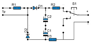 |
| Schematic |
Resistor
R1____________________________3K3
R2____________________________100K
R3____________________________100K
Capacitor
C1____________________________10uF 150V
C2____________________________10uF 150V
Diode
D1____________________________K-200
D2____________________________K-200
Lamp__________________________Fluorescent Lamp
Switch_________________________On/Off
How to test the capacitor which is in the television circuit or the other device are a follows :
- The early circuit of television or other is turned on. Then look at the picture on the screen (for television) . If the images on television rough then opened the real pole. Then the jack that connects the fluorescent lamp is connected to negative leg. If the light is on or blinking so the capacitor is in good condition. But that does not turn mean capacitor is damaged.
- Next soldering in place. Remove capacitor legged leg positive. Connect the cable from the switch . The the switch is pressed. Contacs occur between the components with each other previously linked. When the fluorescent lamp is lit, we can be sure the capacitor is still good. And if otherwise , capcitor is damaged.
Subscribe to:
Posts (Atom)