Showing posts with label timer. Show all posts
Showing posts with label timer. Show all posts
Tuesday, October 8, 2013
Voltage Doubler with NE555 timer chip
This circuit is used to drives relays of 24 and 18 VDC from a 12 Volt power supply. The basic circuit on the IC NE 555 timer and use this circuit with almost any NPN or PNP power transistor.

Resistor
R1 = 47K
R2 = 10K
R3 = 56R
Capacitor
C1 = 0.01uF
C2 = 0.01uF
C3 = 0.001uF
C4 = 0.1uF
C5 = 50uF
Transistor
Q1 = TIP29 , TIP120, 2N4922, TIP61, TIP110, or 2N4921
Q2 = TIP30 , TIP125, 2N4919, TIP62, TIP115, or 2N4918
IC
U1 = NE555

Wednesday, September 11, 2013
Transistor As a timer circuit
Basically on all timer or timer circuit utilizing most of the basic characteristics of the capacitor.
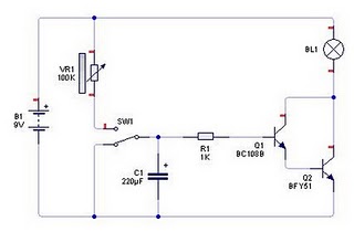
The basic characteristic is the process of filling and discharge that occurs in the capacitor. The length of time charging and release depends on the value of the capacitor.
Read More..
The basic characteristic is the process of filling and discharge that occurs in the capacitor. The length of time charging and release depends on the value of the capacitor.
If we observe the above circuit, the light will immediately switch SW1 turns on when we plug it into potensio VR1, this is because the current flowing from VR1 to trigger the transistor base should fill the first capacitor C1. Semakian large capacitance value of C1 then the longer the time required by the transistor to turn on the lights. Then if we connect it to the Ground SW1 then light would soon die and the capacitor will immediately clear the cargo. So can we draw the conclusion that the transistor can be used as a timer circuit using capacitor charging and discharging properties.
Subscribe to:
Posts (Atom)